Westfield Fasteners Limited Header


Browse Product Range >

Westfield Fasteners Product Specification:

DIN 3021 - Spring band clamp

This product guide contains the specification for Spring Band Clamps, a series of standard parts available from Westfield Fasteners. The basis of this specification is the internationally recognised DIN standard DIN 3021.

Product Description
Spring band clamps are a one piece, bolt free hose clamp made from hardened spring steel. They are designed to be used with hose systems where temperatures can fluctuate significantly. The shape of the spring band clamp will allow the clamp to continue to apply an even and consistent radial clamping force, within a temperature range of -40°C to +120°C. These spring band clamps are suitable for heavy duty applications.

The clamp is opened by squeezing the two ears together. This can be done with pliers or there are specific tools available. The steel clamps are finished with layers of a black chrome (Vl) free coating, which contains zinc.

Scope of the DIN Standard
DIN 3021 specifies the characteristics for this spring band clamp design, made from hardened spring steel for sizes from 13mm to 90mm in diameter. The diameter given (nominal diameter) is the optimum hose outside diameter. The nominal diameter will not be equivalent to the diameter shipped.

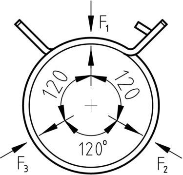
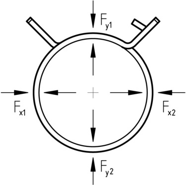
Table 1, with figure 1 gives part dimensions and relevant tolerances. Table 2 gives the 3 directional clamping forces of each clip, whilst table 3 gives the same forces in 4 directions.

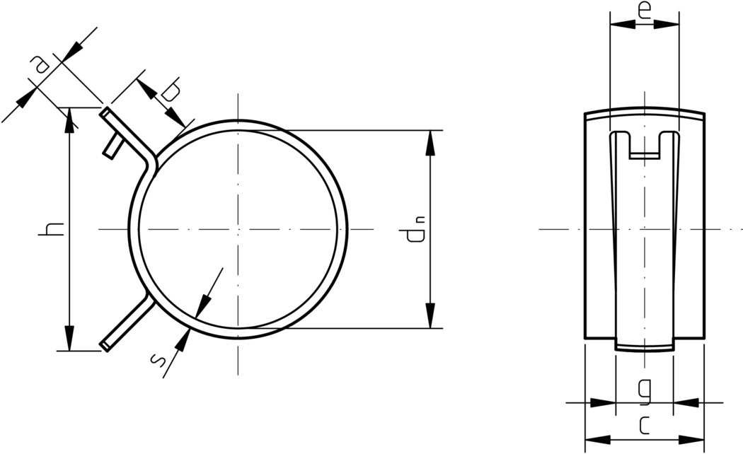
Figure 1: Spring band clamp

Figure 1: Spring band clamp

Table 1: Dimensions & Tolerances according to DIN 3021

Nominal Diameter, dnDelivery Diameter, daFully Open Diameter, d0Material Thickness, s+/-0.4Clamp Width, c+/-0.3a, maxb, maxe, +/-0.7g, +/-0.7h, maxGap Size
131214.20.81291075.8400.09
1413.315.8
151416.5
1614.917.5
1715.618.5
181619
1917.820.21.3
2018.421.6
2119.422.5
2220.524.2
232124.7
242226
2523.526.8
2624.3281.760
2725.229
2826.130.2
292731.5
302832.5
3128.733.5
3229.534.5
333035.5
3430.636.4
3531.538
3632.539
3733.540.3
3834.541.5
393542
4035.542.5
4136.543.52.10.12
4237.544.5
4337.945.5
4438.546.5
4539.547.5
4640.548.5
4741.550
484251
4942.55272
5043.553
514454


Table 1: Dimensions & Tolerances according to DIN 3021 Continued

Nominal Diameter, dnDelivery Diameter, daFully Open Diameter, d0Material Thickness, s+/-0.4Clamp Width, c+/-0.3a, maxb, maxe, +/-0.7g, +/-0.7h, maxGap Size
524554.92.11291075.8720.12
534655.8
5446.556.9
554758
6051.5632.60.15
6557.568
7061.573
756678
807083110
857488
907993


Figure 2: 3-Channel Clamping Force FORM A

Figure 2: 3-Channel Clamping Force FORM A


Table 2: 3-Channel Clamping force for FORM A with width of c=12

Nominal Diameter
Dn
mm
F-3 point
N
Min
13100
14
15130
16160
17
18200
19
20
21
22
23230
24


Table 2: 3-Channel Clamping force for FORM A with width of c=12 Continued

Nominal Diameter
Dn
mm
F-3 point
N
Min
25250
26
27280
28300
29
30
31
32
33
34
35
36
37
38
39
40
41340
42
43
44
45350
46
47
48410
49
50
51
52
53
54430
55
60
65370
70
75330
80300
85
90


Figure 3: 4-Channel Clamping Force FORM A

Figure 3: 4-Channel Clamping Force FORM A


Table 3: 4-Channel Clamping force for FORM A with width of c=12

Nominal Diameter
Dn
mm
Fx
N
min
Fy
N
min
ΔF = Fx - Fy
N
13220170-10 to 140
14
15
16
7
18350280-10 to 180
19
20
21
22
23
24
274403900 to 220
28
29
30
31
32
33
34
35
36
37
38
39
40


Table 3: 4-Channel Clamping force for FORM A with width of c=12 Continued

Nominal Diameter
Dn
mm
Fx
N
min
Fy
N
min
ΔF = Fx - Fy
N
13220170-10 to 140
14
15
16
7
18350280-10 to 180
19
20
21
22
23
24
274403900 to 220
28
29
30
31
32
33
34
35
36
37
38
39
40


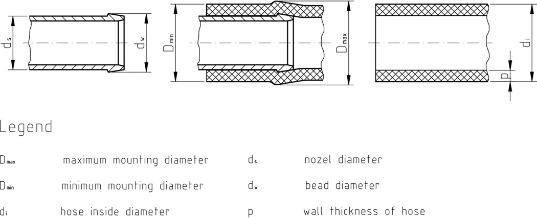
Figure 4: Pre-Selection of the Nominal Diameter

Figure 4: Pre-Selection of the Nominal Diameter


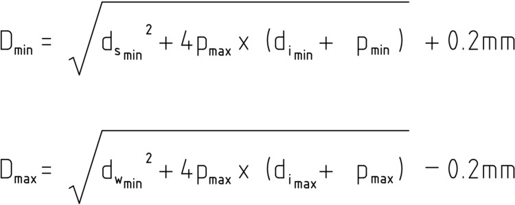
Figure 5: Area of Application Equation fot Calculating the Dmin and for DnMax

Figure 5: Area of Application Equation for Calculating the Dmin and for DMax


For further details, please refer to the DIN standard document for this item.